Showing posts with label earth resources. Show all posts

Sunday, March 24, 2024

More blue water - why is the Nil Diya Pokuna blue?

On my last visit to Sri Lanka, I was keen on exploring some lesser-known attractions and decided to visit Nil Diya Pokuna (නිල් දිය පොකුණ) located close to Ella in the Uva Province. I was impressed and fascinated by the massive underground cave complex and the blue water pond at the end of the 850m hike through the cave. This was the second time I saw clear blue water in Sri Lanka, the first being in a limestone quarry.  

The usual reason for ponded water to appear bright blue or turquoise in colour is the fine particulates that selectively scatter light through water (the same reason why the sky is blue). In the case of the limestone quarry the fine particulates are minute calcite crystals and in the case of glacial lakes they are finely ground rock particles known as glacial flour. 

Nil Diya Pokuna has a very interesting geology, with several different rock types present around and within the caves, and I wanted to understand what gives the water its blue colour. Caves of this scale are usually formed by the action of weathering and erosion of sedimentary rocks such as limestone. However, this region of Sri Lanka consists of primary of metamorphic rocks. This blog post by Dr Jayasingha describes the geological origins of the cave complex containing Nil Diya Pokuna. According to it, the caves have been formed by the initial dissolution of Marble, which leads to weakening of rock joints and bedding planes and subsequent collapses of the other rock masses creating the large underground caverns. 

Marble is formed by the metamorphosis of limestone, and its dissolution would lead to the release of calcite crystals. There are stalactites formed at several places within the cave, as seen in the photos below, that confirm the occurrence of marble or limestone dissolution. Therefore, it is reasonable to conclude that the reason for the blue coloured water in Nil Diya Pokuna is the calcite crystals that are accumulated in the water as it flows through the joints and fissures in rock containing marble or limestone before making its way into the pond. Below are some photos from my visit:

Stalactites in the cave indicating marble or limestone dissolution
 
Evidence of weathering and staining in the rock

Visible bedding planes and smooth joint surface of a possible collapse leading to cave formation

Blue water and more stalactites

High water levels were blocking off some more expansive areas of the cave

The water was a little murky due to recent rains


Wednesday, January 4, 2023

Estimating surface settlement induced by underbore or tunnel construction

It is often necessary to estimate the potential ground surface settlement caused by underground infrastructure projects involving tunnels and underbores. Such settlement assessments are used to determine if any additional protection works are necessary particularly if underbores are tunnels are to be constructed underneath roads, railways or buildings. Finite element analysis programs such as Plaxis 2D/3D, Optum G2/G3 or FLAC are typically used to model settlements in such instances. Accurate information on ground properties, tunnel parameters and loading conditions is required to provide accurate settlement assessments. 

In situations where a quick estimate with minimum data inputs is required, a common semi-empirical method developed by Peck (1969) is also commonly used. This method is based on field observations made by Peck, and the ground settlement trough profile is approximated by a Gaussian distribution curve. The volume loss in the tunnel (overbreak or annular collapse) is equated to the area under the Gaussian curve from which a settlement profile is generated. The width of the settlement trough varies between soil types and is controlled by a parameter (Kg) that is specified for different soil types and strengths. I developed a web application (https://underbore-settlement.anvil.app/), also embedded below, to estimate settlements based on the Gaussian curve method developed by Peck.


It should be noted that since this method does not consider any volume change in soils (consolidation or dilation), it is valid only as an initial estimate under short-term conditions. 

The figure below shows results from the above method compared to the results from a simple Plaxis 2D model. A tunnel with 1m diameter and 2m of cover subject to a volume loss of 10% bored through undrained soft clay and loose sand was modelled separately in Plaxis 2D to compare against the results using Peck's method with recommended numbers for Kg, for clay (0.5) and sand (0.3) respectively.

Comparison between Plaxis output and Gaussian curve method by Peck (1969)

It can be seen that the results from Plaxis and Gaussian curve method are similar for sand, but varies slightly for clay. Using a Kg value of 0.7 for clay leads to a curve very similar to the Plaxis 2D output. The choice of Kg for various soil types with different strengths is a subject of research, and available literature suggests that a Kg value of 0.4-0.7 is appropriate for soft clays. However, with an understanding of the limitations of the Gaussian curve method, it can be used as a rough initial estimate of settlements before embarking on detailed finite element analysis. The web application linked above will be useful for such quick assessments. 


Saturday, November 23, 2019

Backfill for underground infrastructure: Soil strength or corrosivity? Which do we choose?

This post is inspired by one of my research findings published recently. My PhD research involved the evaluation of underground corrosion from a unique viewpoint combining the two traditionally separate fields of soil mechanics and electrochemistry.

Corrosion requires both water and oxygen to occur, and in the case of underground corrosion, soil supplies these reactants for the reactions to proceed. It follows that the ability of the soil to store and supply water and oxygen will to some extent, govern the rate of corrosion of metal buried in soil. It is known that there is a critical level of moisture at which corrosion is soil is maximized. Too much water will stifle corrosion because the supply of oxygen to metal is severely limited under waterlogged conditions.

As part of my research, we investigated these mechanisms in detail. Buried infrastructure such as pipelines and storage tanks fail due to corrosion, causing large economic losses and environmental damage due to leaks and bursts, exposing contents such as oil and gas to the surrounding environments. An understanding of underground corrosion and its prevention helps increase longevity of such buried assets and is a step towards sustainable development. While corrosion and its prevention are handled by electrochemical practitioners, the installation of buried infrastructure and backfilling is under the purview of geotechnical engineers. Given that the problem of underground corrosion overlaps both these fields, its study should be an interdisciplinary effort.

Our experiments showed that the critical level of moisture for corrosion is related to a relationship known as the soil water retention curve, or the soil water characteristic curve. Combining results from several electrochemical experiments and soil tests we were able to identify the behavior of water in soil that governs corrosion. We saw that in different soil types, the continuity of air and water phases change differently with the degree of water saturation, and that the transition point at which the air phase becomes occluded coincides with the critical degree of saturation for corrosion (where corrosion is maximized) for each soil type. What was more interesting was that this critical water content for corrosion is the same as the optimum water content for soil compaction. It has been shown that the same mechanisms for air entrapment occurs at the optimum water content during soil compaction.

This finding is important because, it is usual practice among geotechnical engineers to compact soil to its optimum water content to maximize its strength. In the installation of buried infrastructure and the subsequent compaction of backfill, if this usual practice is followed, we will be inadvertently creating the most conducive conditions for corrosion of the buried metallic asset. So, the question is whether we increase our soil strength, of the rate of deterioration of the buried metal. One possible solution is to compact soil in the drier side of the optimum water content. But there may be other factors at play that need to be considered. What is more important is to identify that this problem is interdisciplinary in nature and needs to be solved that way. Corrosion engineers need to be aware of this in planning prevention techniques such as cathodic protection, and geotechnical engineers need to know the effect of soil compaction on the corrosion of buried metallic infrastructure.

Like many of our modern problems, underground corrosion needs to be viewed and solved by taking a multidisciplinary approach. Confining our engineering efforts to the traditionally isolated fields is likely to worsen the problem rather than solving it, and our knowledge and forces need to combine to achieve sustainable progress.

The point of maximum corrosion was identified as the degree of saturation at the inflection point of the water retention curve also coincident with the degree of saturation at the optimum moisture  content (OMC) in the compaction curve

Thursday, May 17, 2012

"I drink your milkshake!!"

Arguably one of the best movies of the decade, the movie "There will be blood" perfectly encapsulated the the ugly side of the oil industry. It showed how the power hungry and powerful people exploit the weak and the evil effects of greed. While some may argue that those savage days are behind us, what happens today is more or less the same thing, done only with a mask of so-called civilization.

There are numerous examples in today's world of the strong exploiting the weak, and it often goes to the extent of invading someone else's land just to exploit its resources. Due to this reason a cloud of uncertainty and danger looms over any nation that already has or are about to discover natural oil reserves in their land, for they are under the risk of an invasion. It is also a well accepted that if a third world war is to occur it will be over crude oil.

The recent discovery of possible petroleum deposits at the Mannar Basin in Sri Lanka, brought a lot of excitement with it because if commercially exploited,(which has been proved possible) it would be a great boost to the country's economy. However it also is a matter of concern because recent developments in similar countries were not what you would expect in a civilized world. This is why when moving into the world oil industry we must be careful, because we don't wan't anyone else drinking our milkshake.

too late, I drank your milkshake!  image from - wikipedia


Friday, April 13, 2012

Preparing a Thin Section of a Rock

Thin sections of rocks are prepared in order to observe them in Petrological Microscopes. Thin sections are prepared by grinding rocks to a thickness of micrometers  (0.03mm) so that its features such as mineral grains, cleavages, twinning and optical properties of those minerals can be observed.

thin section of Gabbro - image from wikipedia

The procedure adopted in preparing thin sections is explained below.

1.  The sample to be sectioned and is determined and the direction of the cut is selected such that it is cut across structures such as layering, foliation, cleavages etc.

2.  A rectangular slice having a size of about 3x2x0.5 cm is cut using a diamond wheel.

3.  One surface of the slice is polished using Carborundum powder from coarse to fine varieties.

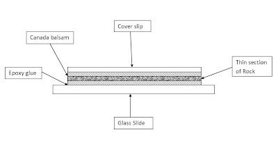
4.  The polished specimen is mounted onto a glass slide, polished side down using epoxy glue. (Care should be taken to avoid air bubbles)

5.  The other side of the rock specimen is ground and polished using carborundum powder to bring the thickness of the section to 0.03mm.

6.  The cover slip is fixed onto the polished section using Canada Balsam. (The cover slip protects the thin section)

The following diagram depicts the prepared thin section (thicknesses are exaggerated for clarity)

thin section 

This method is used for preparing thin sections of hard rocks. In order to prepare a thin section from a soft rock, first the rock must be strengthened using a glue, and the same procedure must be followed.

Sand grains can be directly mounted on Canada Balsam and polished if necessary before covering with a cover slide. This method is used to observe the interior of individual grains of sand.


Parts of a Petrological Microscope

A Petrological Microscope also called a Polarizing Microscope is an essential instrument in optical mineralogy and Petrology. It is used to observe thin sections of rocks under polarized light and to identify their physical and optical properties. The microscope is widely used to identify and classify rocks and minerals. Given below is a schematic diagram of a petrological microscope and its parts.

parts of  a petrological microscope

The function of each part are as follows,

Light Source - Provides light into the microscope for viewing. Usually an electric bulb or a two sided(plane and concave) mirror.

Polarizing unit 1 - This converts normal light into plane polarized light and is situated below the microscope stage.

Condenser System - This removes the effects of interference of light by changing the phase of light.

Diaphragm Lever - This lever is used to control the intensity of light.

Microscope Stage - This is a graduated, rotatable disk on which the thin sections are mounted for viewing purposes.

Objective - This contains several objective lenses of different magnifying power that can be selected. These lenses are of usually of three types. Low power objectives(3.5x) that provide a large coverage of the thin section where the micro-structures and grain percentages can be observed, Medium power objectives(10x) that shows several grains in considerable detail and can be used for identification purposes, and High power objectives(40x-50x) that show a single grain in very fine detail and used for advanced analysis.

Slot - the slot is used to insert accessory plates for different viewing purposes.

Analyzer (polarizing unit 2) - This is also a light polarizing unit. However the plane of polarization is perpendicular to that of the polarizing unit that is situated below the microscope stage. This can be set in either "in" or "out" positions.

Bertrand lens - This is a special lens system that is used to observe interference figures. This too can be ste in either "in or "out" positions. When the Bertrand lens is in the "in" position, the view seen from the eyepiece is smaller.

Eye piece - This is the lens through which the observer views the thin section. It has a circular view with centre cross-hairs to help viewing.

The petrological microscope can be set up in two arrangements depending on viewing purposes and optical properties of the minerals. They are,
1.  PPL arrangement (Plane Polarized Light) - analyzer is out, Bertrand lens is out
2.  CPL arrangement (Cross Polarized Light) - analyzer is in Bertrand lens is out.


Tuesday, April 10, 2012

Sand Mining and Storm Damage

Beach sand mining has increased during the past few decades as river sand has gradually depleted causing several environmental problems. Beach/sea sand is not suitable for construction purpose as a replacement for river sand due to its salinity. The salinity in the sea sand can corrode steel reinforcements and cause structural failures if used in concrete. However the sea sand can be thoroughly washed to remove its salinity before using it for construction purposes. Due to this reason beach sand is mined increasingly in order to avert the environmental damage caused by mining river sand.
This is not a good solution because beach sand mining has its own harmful side effects. While most will agree that offshore mining is not very environmental friendly few realize that beach sand mining is as catastrophic. The sand on the beach and in the sea belong to one dynamic system. Removing sand from the beach therefore will disturb this balance.


image from http://www.seafriends.org.nz/oceano/beach.htm


This is what a typical healthy beach looks like. Even the sand far away from the water are part of the beach. The dunes on a beach serve a purpose.

image from http://www.seafriends.org.nz/oceano/beach.htm


The above picture depicts the behaviour of the sand during a storm. Note how sand is borrowed from the fore dunes to create a bank below the sea level. This bank helps to break the waves and dissipate energy thus minimizing the damage caused by the storm.
So what would happen if the sand is carelessly removed from the beach? There wouldn't be a way for the beach to adapt during a storm. This will lead to severe inundation and damage.
The sand in a healthy beach undergoes a cycle known as the "beach cycle". The beach continuously adapts by moving sand and sediments and rebuilds itself after storm damage by itself. Removing sand from the beach could disturb this cycle and cause long term effects such as severe coastal erosion. This makes it necessary to explore alternative methods to mine sand. Deep sea sand mining, carried out far away from the coast could be a possible solution although its effects and impacts should be thoroughly assessed first.

Sunday, February 26, 2012

Earth's Structure

In a previous post of mine named Onion Earth I explained how the earth has a layered structure somewhat resembling an onion. The earth has several layers such as crust, mantle core, asthenosphere, mesosphere etc. Some of these layers overlap each other and thus can create confusion. This problem could be avoided by classifying these layers in two ways, one based on the Chemical composition and the other based on the physical properties.

Based on Chemical composition, three layers are identified.
1. Crust  -  Abundant in elements Si , O, Al, Mg, and Fe
2. Mantle  -  Mainly Fe, Mg, Si
3. Core  -  Ni and Fe alloy

Based on the physical properties five layers are identified.
1. Lithosphere  -  Rigid outer shell. Comprises of the crust and uppermost mantle
2. Asthenoshpere  -  Shows plastic behavior. Lithosphere "floats" on this layer. 5% of rocks in this layer is molten
3. Mesosphere  -  Extends from about 300km to 2000km beneath the surface. Solid
4. Outer Core  -  Molten. Rotates around the inner core and produces the earths magnetic field
5. Inner Core  -  Extreme pressure causes it to stay solid despite the high temperatures

Source : http://www.tulane.edu/~sanelson/images/earthint.gif

Sunday, February 19, 2012

A Classification of Ocean Waves

The sight of waves breaking at a shore is common sight to most of us. While it is relaxing to watch the constant pounding of the waves while listening to the hum of the sea, we don't give much thought to the way these waves are formed or the types of waves in the ocean.
Ocean waves are classified into seven major groups depending on their size, period and way of formation. These types are described below.

1. Capillary Waves
Capillary waves are the smallest of these types, having a period generally less than 0.1sec and a wavelength less than a couple of centimeters. Capillary waves are caused by local winds, more specifically short bursts of winds. Capillary waves are similar to ripples created on a body of water by dropping an object into it. The restoring force in the case of capillary waves is surface tension

2. Chop waves
These are the the common waves in the ocean familiar to everyone. These waves have periods of several seconds, and wavelengths ranging from 1 to 10 metres. Chops are wind generated waves. A consistent blowing of find over a considerable fetch(sea surface area over which the wind blows) causes these waves. The restoring force of these waves is gravity.

3. Swells
Swells are much larger wind generated waves. Very powerful winds are required for the creation of these waves and they are related to distant storm surges. Periods can vary between 10 and 30 seconds and wavelengths are in the order of hundreds of metres. Swells occurring alongside a storm in coastal ares can have devastating effects.

4. Seiches
Seiches are standing waves that can be created by wind, seismic disturbances or by tidal resonance. The word seiche originates in a Swiss French dialect word that means "to sway back and forth". This an accurate description of the wave because it actually sways to and fro like a see-saw. These waves can be generated at harbours, estuaries, lagoons and even swimming pools. You can visualize a seiche by giving a nudge to your tea cup. The resulting oscillatory motion of the liquid in the cup is similar to that of a seiche. Seiches can have periods ranging from a couple of minutes to several hours and wavelengths upto hundreds of kilometres.

5. Tsunamis
Tsunamis are massive and catastrophic waves generated by submarine disturbances. Two major tsunamis have occurred during the past decade causing severe destruction to places affected. The most common submarine activity leading to tsunamis is subduction between tectonic plates. However other disturbances such as landslides could also produce tsunamis. Tsunamis can have a period of about an hour and wavelength can reach hundreds of kilometres.

6. Tides
Tides that are caused by the gravitational attraction of the sun and moon are familiar to us but few realize that it is classified as a wave. Tides have periods of 12.8 or 24.8 hours and are related to the earths speed of rotation. Wavelengths are in the order of thousands of kilometres.


Tuesday, December 6, 2011

The unseen side of Graphite mining

Graphite is a major export of Sri Lanka and is mined at two places in the country namely, Kahatagaha and Bogala. Sri Lanka is the only country in the world where crystalline graphite or lump(vein) graphite is mined underground. The graphite such mined is also of very high quality and is very pure-99%pure C.

Graphite -image from Wikipedia


In a very brief report I wrote about the graphite mining practices in Sri Lanka, based on an investigation carried out at the Graphite mine in Kahataga, I concluded that no overall damage to the environment was done. This was because graphite being a natural product and is essentially pure carbon which is not a toxic substance, it cannot do any harm to the environment. However further research and more thought put into the matter shows that I couldn't have been more further from the truth. Graphite mining, just like any other mining has a considerable impact on the environment and can lead to catastrophic result if preventive measures are not implemented.

Mining graphite involves the use of explosives to crack open the rock joints and to expose the graphite. The amount of explosives used in this process is often more than what actually is required and therefore ends up creating damage to unintended areas as well. this process also result in the release of dust and very fine particles of Carbon into the atmosphere causing air pollution. This can lead to the deterioration of   the health of workers and people living in the vicinity.

Mining graphite is followed by the processing at the site itself. This processing of Graphite also has a negative impact on the environment of its own. In addition to releasing a larger amount of fine graphite particles into the atmosphere the graphite powder spillages can cause soil contamination and cause harmful effects to flora and fauna.

The underground mining process has a separate set of impacts. The emptying of fissures in the rock and the separation of rock joints can cause water to seep through them and eventually lead to landslides that can destroy the whole area. Furthermore the structure of the dug mine can result in the alteration of water tables causing a heap of environmental impacts. Disturbing the natural water cycle and introducing contaminants can cause damage to both nature and humans. 

To avoid or minimize these harmful impacts, the mining will have to be done after thorough planning with thought given to the environment as well as economic benefits. After mining the land will have to restored to its previous state to bring back the balance. Care should be taken regarding the the chemicals and explosives used in the process and also the wastes generated and discharged. By adopting these practices and through implantation of concepts like cleaner production Graphite mining can be made more environmentally friendly.

Sunday, October 23, 2011

Volcanic Glass

There are three types of rocks on earth. They are IgneousSedimentary and Metamorphic rocks. Igneous rocks are formed by the solidification of magma and are further divided into two types, Namely, Plutonic rocks(Intrusive igneous rocks) and Volcanic rocks(Extrusive igneous rocks). Plutonic rocks are the rocks that are solidified inside the earth and are usually crystalline in nature due to the slow cooling process Thus they have a coarse grained crystal structure. Volcanic rocks however solidify muck quicker and therefore often show a very fine grained crystal structure. If the cooling and solidification of the volcanic rocks happen even faster it leaves no time for crystal formation. This makes the volcanic rocks amorphous and therefore have properties of a supercooled liquid. That is, These rocks have a glassy texture and are brittle like glass. They also exhibit a conchoidal fracture just like glass. One such rock is Obsidian. Obisidian looks almost artificial and has a remarkable appearance. They are sometimes used to fashion precision cutting tools such as surgical knives. Obsidian has such an appearance that it is hard to believe that it actually is a rock and that it is formed naturally.. It looks artificial. It is a remarkable product of Earth's natural geology. Here's a picture of Obsidian.

Sunday, March 13, 2011

Engineering with Responsibility

The crisis the Earth faces today is not a secret, almost everyone knows about it but very few take it seriously. Chances are that someone reading this post might also disregard this by saying "just another global warming message....".

However, the problems we face today are not limited to global warming... Pollution is at an all time high, Several species have become extinct or are in the brink of extinction, Natural disasters are becoming increasingly common, the list goes on... Clearly there is something wrong, and we humans are responsible.

Our actions, especially engineering ones have disturbed the "balance" in nature causing ecosystems to fall apart and create catastrophe in the process. All disasters we face today are either caused by us, or its destructive effects are magnified by our actions. For example, Sea erosions and tsunamis hit us harder because we excavate and remove all the natural coral reefs in the coastal area which would otherwise serve as a very effective natural wave breaker. Also filling of marsh land increases the likelihood and severity of floods.

But some people justify these actions by saying that it is necessary for development and improvement of our lifestyle... or these are minor side effects of engineering a better world. All these claims are false. How can we say we are developed when we face natural disasters almost everyday? Engineering that does not go hand in hand with nature is not engineering but "Reckless building".

Engineering encompasses the ideas of creating with care and concern for the surroundings, managing resources efficiently, and ensuring sustainability. Engineering which neglects the above aspects cannot simply be called Engineering. Fortunately, as of recently more attention has been given to this area resulting in looking for ways to protect nature and the environment. Emergence of new fields of Engineering such as Environmental Engineering and Earth Resources Engineering is a promising trend.

It is very important that we take the task of protecting our earth very seriously. Engineers need to work with responsibility. The only way of improving ourselves is by protecting nature and using its resources carefully and efficiently.

What we should understand is that all the resources on earth are limited. Therefore we must use them with extreme care. After all, Earth is all we have got, We don't have another planet to go to...
see what I mean: http://www.oneearth.org/